|
Area51 Project Argo - New Electrical System:
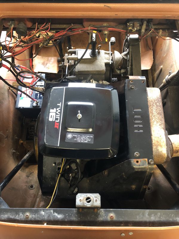
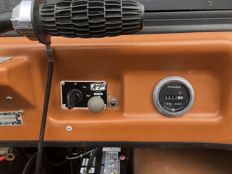
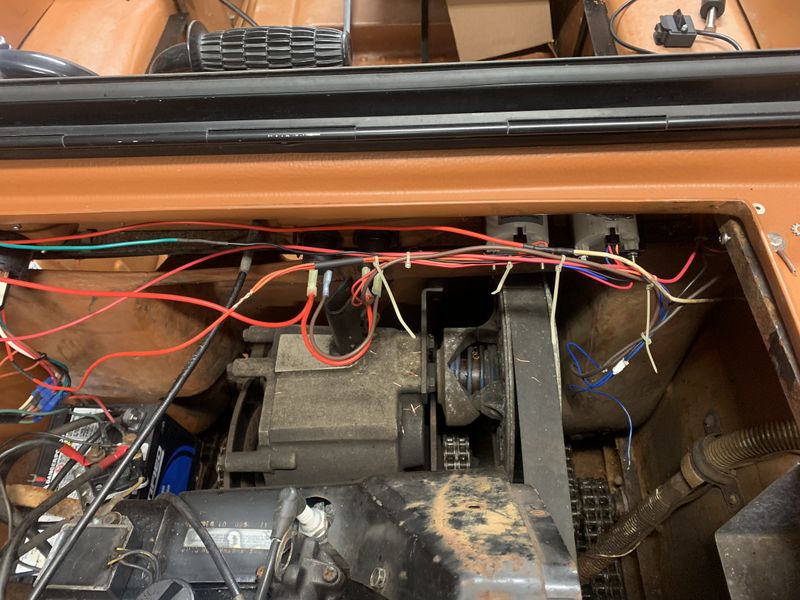
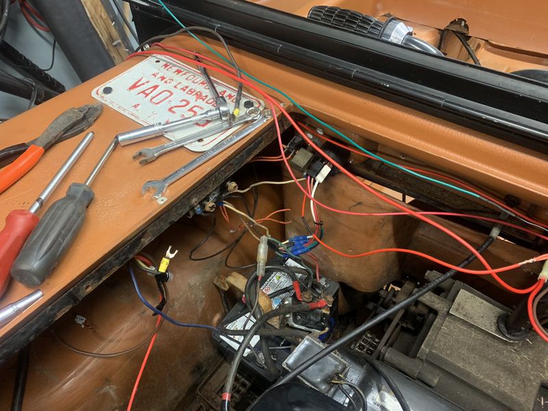
The electrical system on my '89 Argo was pretty basic, it used glass tube style fuses in holders scattered all over the place, and key on accessories were switched mechanically through the ignition switch. As I would be adding more and modern accessories to this machine I wanted to rebuild the electrical system using relays and a centrally located power distribution centre.
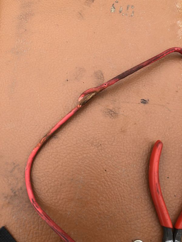
Even the old winch wiring didn't hold up well. At some point the positive lead became pinched and created a dangerous short to ground.
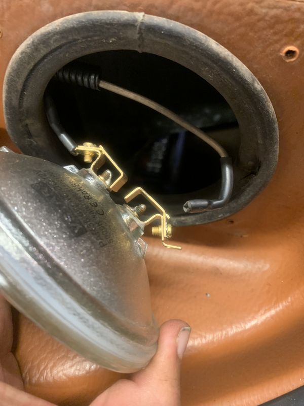
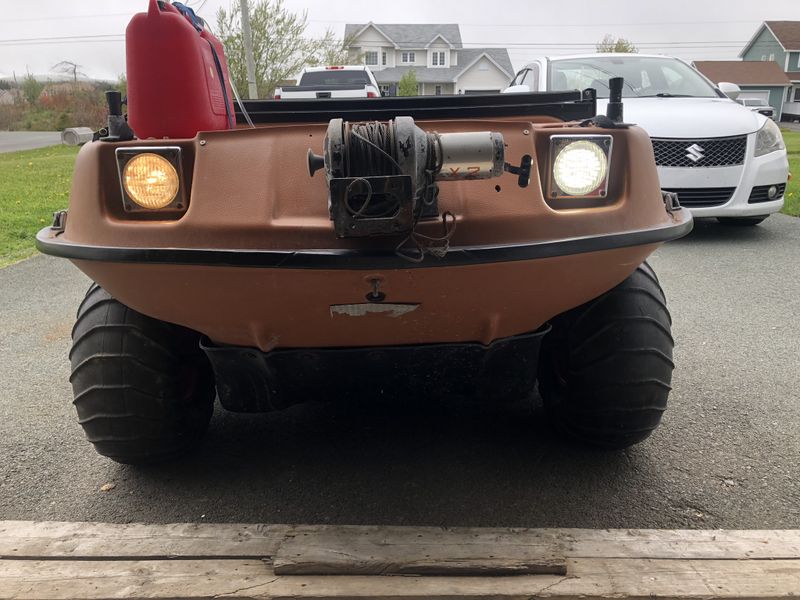
One of the first upgrades was this set of fantastic replacement headlights from ArgoAdventure.com.
They sell an OEM style sealed beam glass headlight outfitted with powerful LED's which are much brighter than stock but retain the original look of the machine.
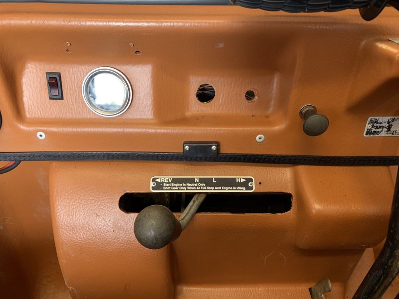
Next I could finally stop hot wiring the ignition to start the Argo (previous owner lost the key) by installing my brand new plug and play ignition switch sourced from the dealer. The new switch needed a slightly larger hole but plugged into the factory harness without modification.
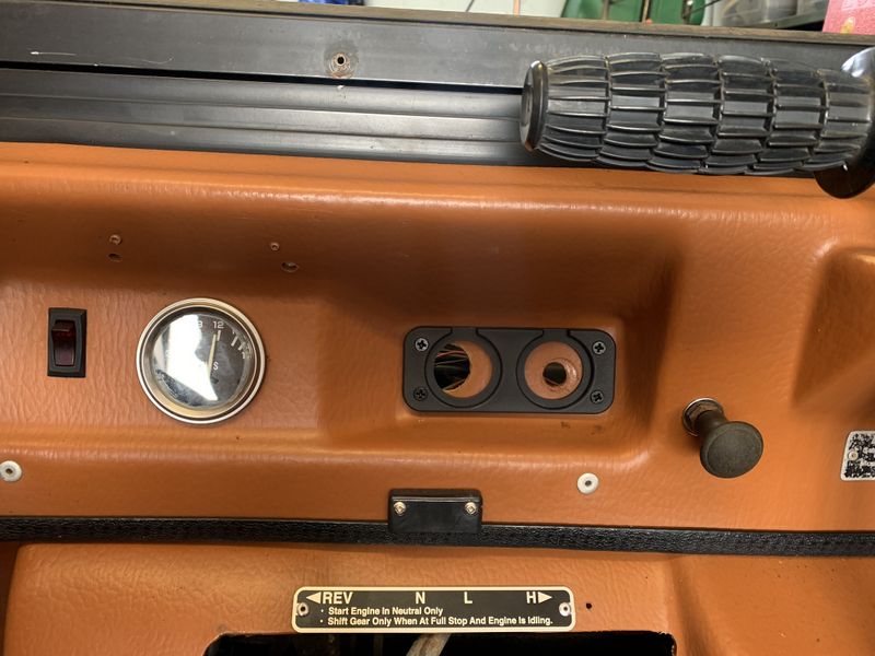
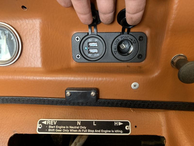
Next up on this project was replacing the rusted out 12v accessory plug dad installed decades ago. I moved the choke lever over to the right to accommodate the new plugs.
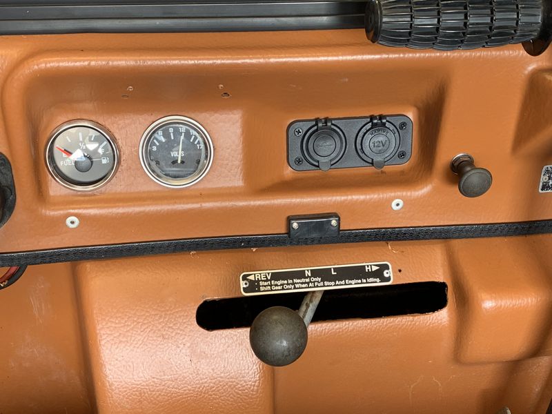
The mounting plate for my new EBay dual accessory outlets fit the nook perfectly, as if it was designed just for this machine!
The new plugs are weather resistant with nice rubber caps on each.
The left houses dual USB charging ports and the right is a standard cigarette style 12v plug in.
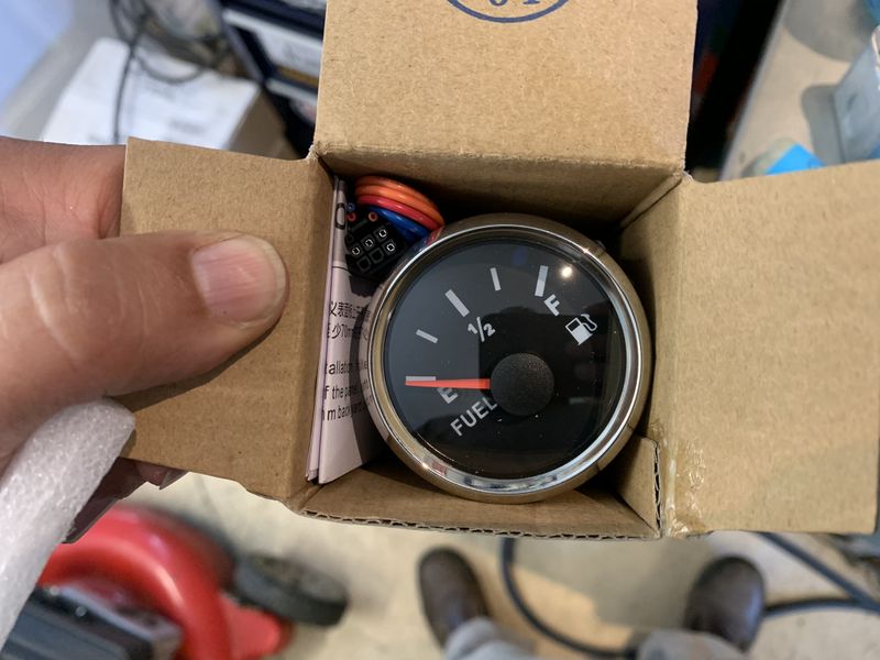
My next EBay purchase was a new Voltmeter to replace the defective one in the machine, unfortunately a fuel gauge arrived. LoL The seller was great and re-shipped a Voltmeter and threw in a sending unit for the fuel gauge at no charge.
The new Fuel gauge was installed to the left of the Voltmeter.
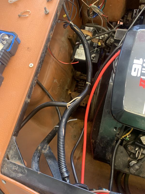
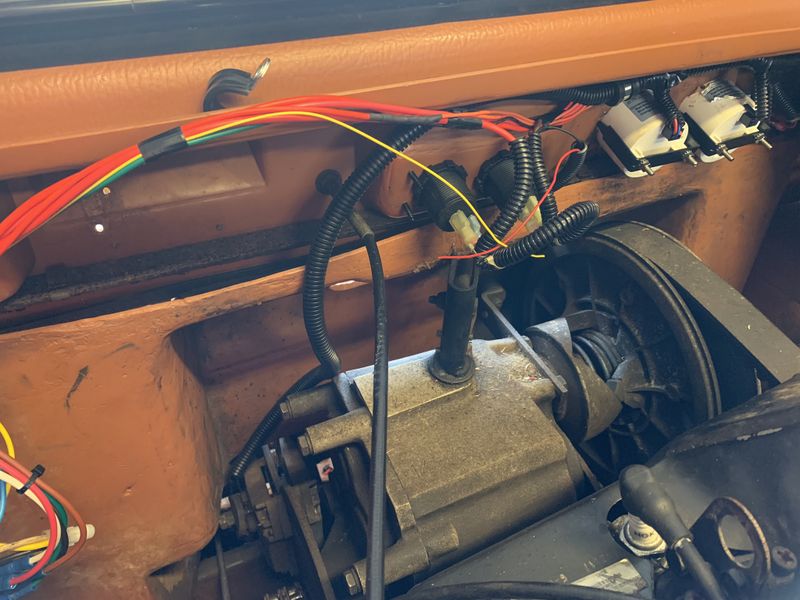
I started rebuilding the wire harness using the OEM wiring to the voltage regulator, ignition coil and headlights but wrapping them in protective wire loom and neatly ty-wrapping it in place.
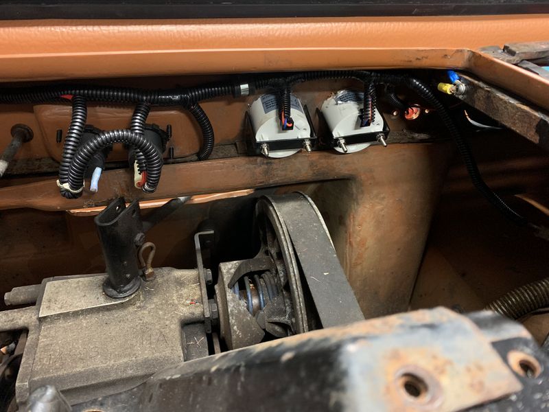
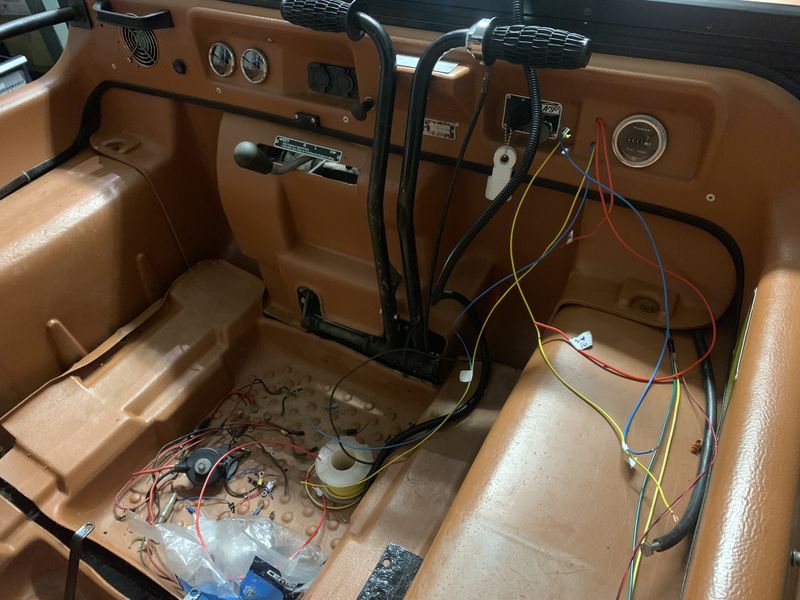
I completely removed all of the old dash harness which consisted largely of the old winch controller wiring. I began building the new harness ty-wrapping everything to keep the wire lengths nice and neat while I terminated the connections at the gauges and accessory plugs.
When all the connections were soldered and heat shrank I removed the ty-wraps and replaced them with tape to keep everything neat and organized before installing protective wire loom.
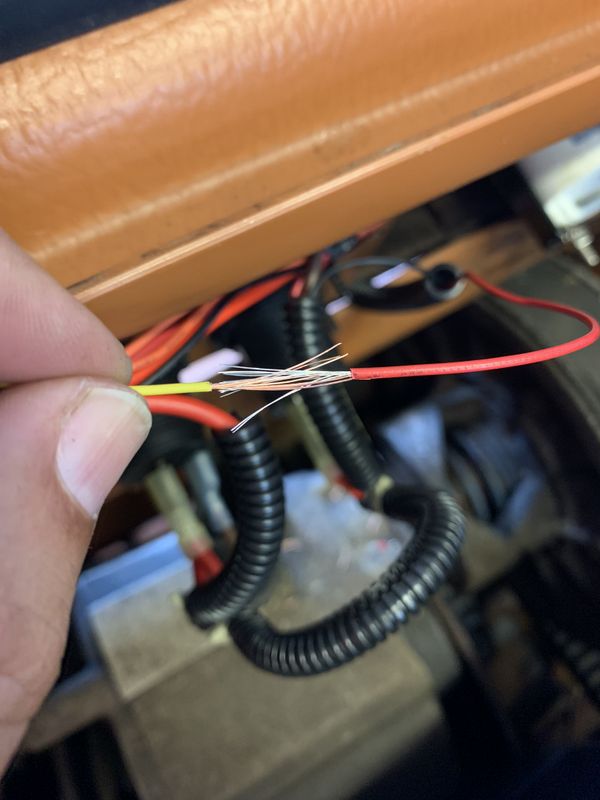
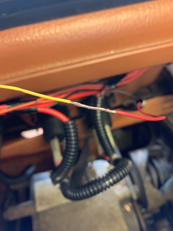
Couple pics of inline wire splicing
Key to a good connection is a good tight physical twist in the joint. Last step after twisting is solder to hold the joint permanent and glue lined heat shrink for maximum corrosion resistance.
Loom was installed then the whole harness neatly bolted to the body using rubber lined wire clamps and stainless hardware. I created left and right side engine bay grounding points to keep the harness neat and more organized. Colour codes such as using red wire for positive, yellow for relay switched power and black/brown for grounds keep the whole system tidy. Wire size was determined based on load and a fuse size chosen based on wire size.
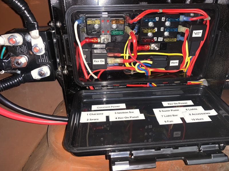
The new power distribution centre consists of 2 fuse panels. The first 4 port panel is for Constant Power which includes charge feed in from the voltage regulator, 12v power to the ignition switch, and a 30 amp feed through a relay to energize the second fuse panel only when the key is on. This way there is no load through the ignition switch anymore and all of my accessories will power off when the key is off for safety and to prevent accidental running the battery low.
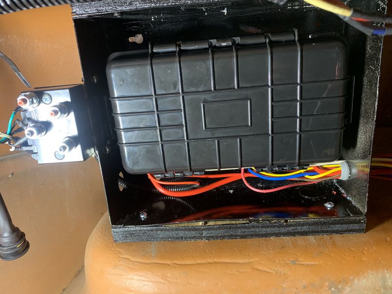
The fuse panels & relays were mounted in a locking plastic weather resistant enclosure which I riveted inside an old alarm panel. This provided structural support and a place to mount the winch contactor.
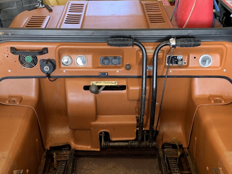
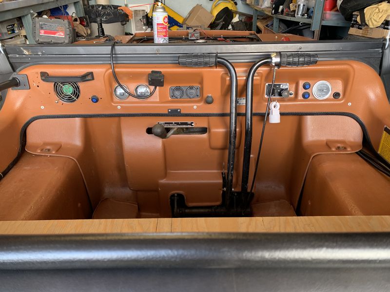
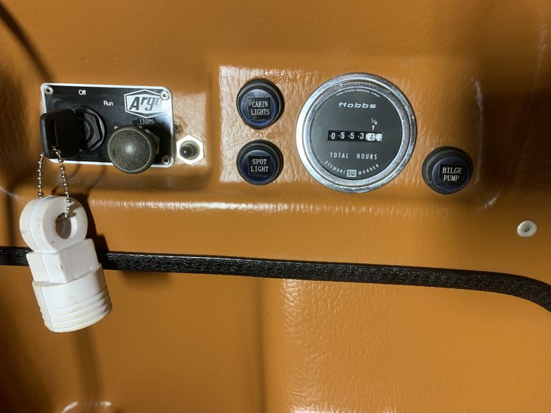
The almost completed dash layout & wiring. The blue switch on the left controls the heater fan used mainly when the canopy is installed, the two blue switches stacked to the right control the red interior LED's and a future LED light bar which is completely pre-wired, the last switch on the right side is for the bilge pump.
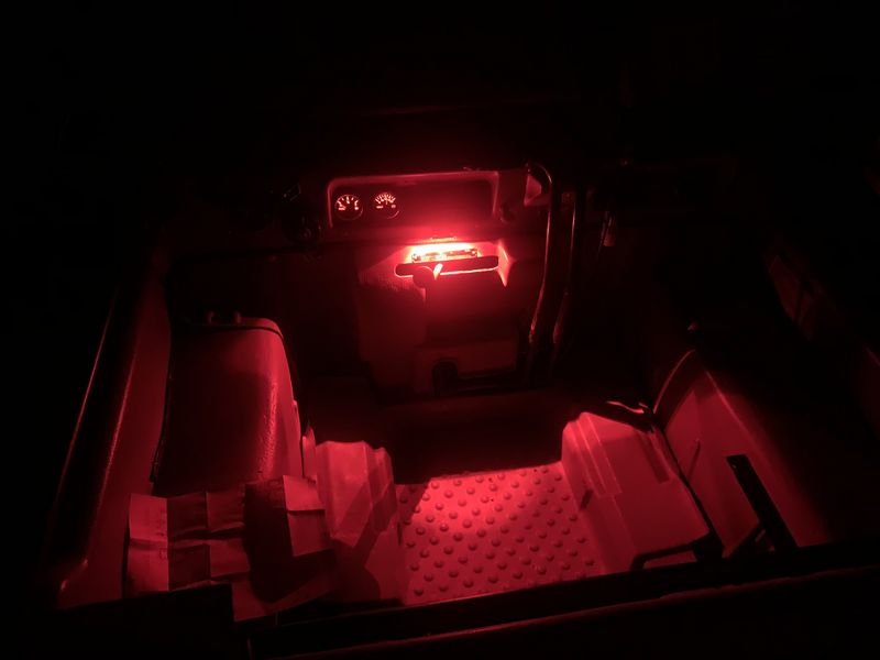
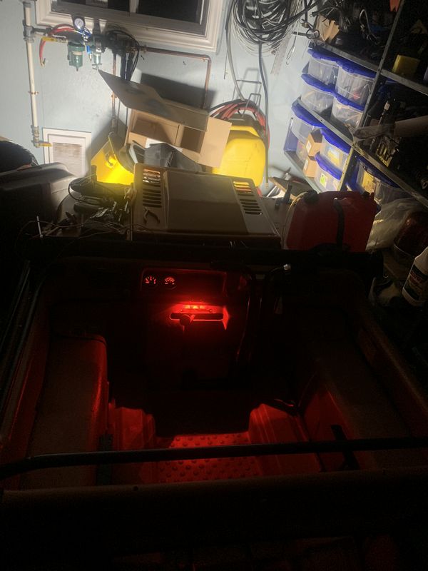
Interior red LED lights front and rear and gauge backlighting is wired to the main headlights, although they may end up on their own switch if I find them too bright with the Canopy installed.
A couple weeks later my glow in the dark decal sheet arrived from EBay to make it clear exactly what each switch is for!
The new headlights are awesome and I'm really happy with the red interior lights. In French's Argo we found them convenient particularly if you drop something on the floor at night and they don't produce glare. The backlighting of the gauges is wired to come on/off with the headlights.
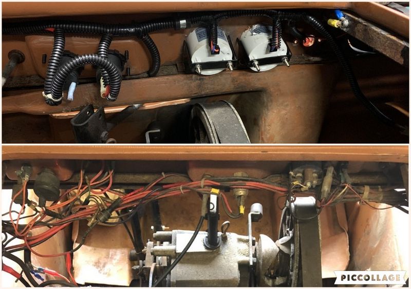
Quick after photo on top and before photo on bottom of the Argo's electrical system.
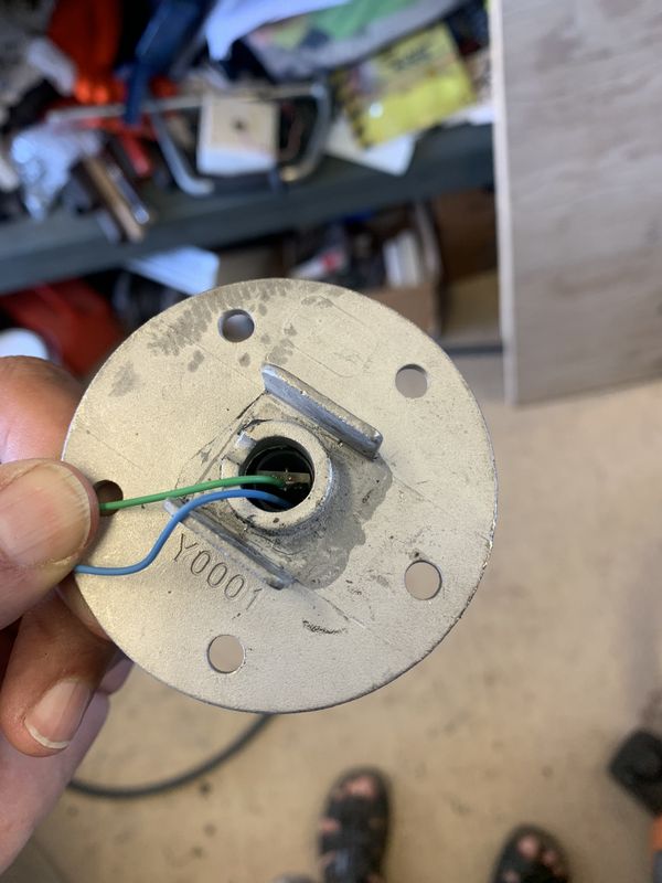
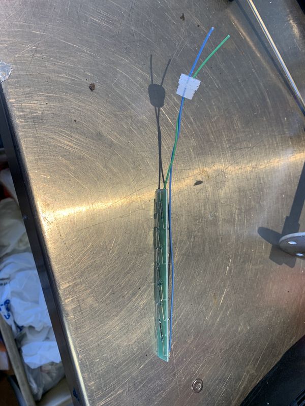
Next up was installing the fuel gauge sending unit. This is a sealed unit that uses a round black plastic float outside a welded stainless tube. The float has magnets which operate micro switches/resistors inside the stainless tube to indicate fuel level. This particular unit read backwards on my EBay fuel gauge, a 2nd sending unit did the same thing.
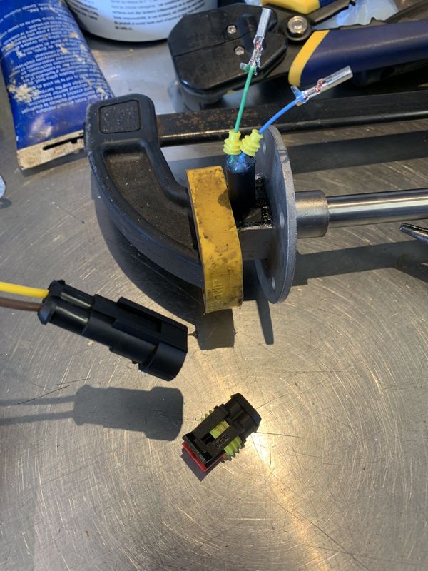
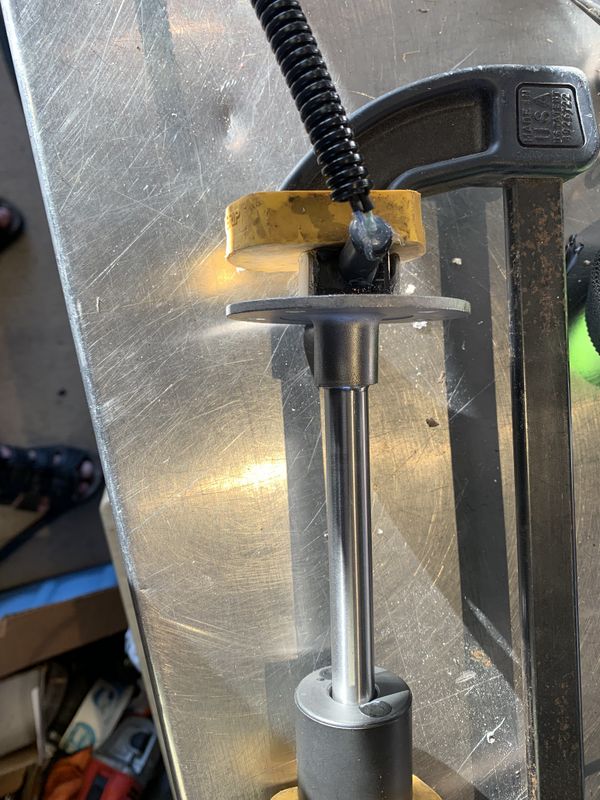
I took the unit apart, turned the board upside down, soldered on extended wires and reinstalled. The portion of the sending unit I opened is outside the fuel tank so its still perfectly safe.
I reinstalled the rubber cap and sealed it with silicone just as the manufacturer had done previously. I clamped the repaired unit for a couple days to ensure the glue fully cured.
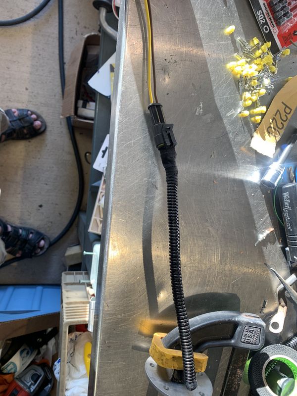
I chose to install a single pair weather pack connector so that the sending unit could be easily unplugged if the gas tank has to be removed in the future.
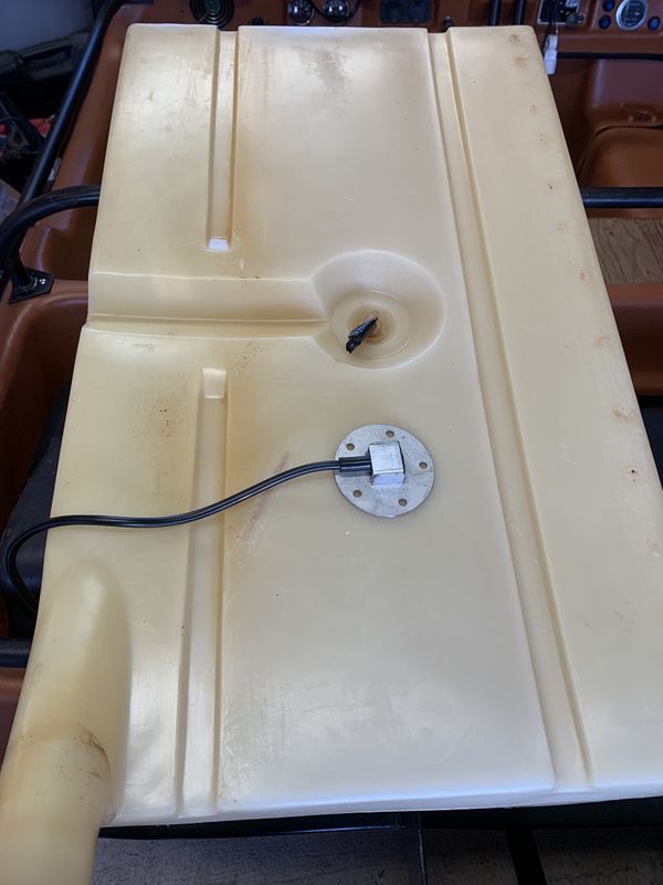
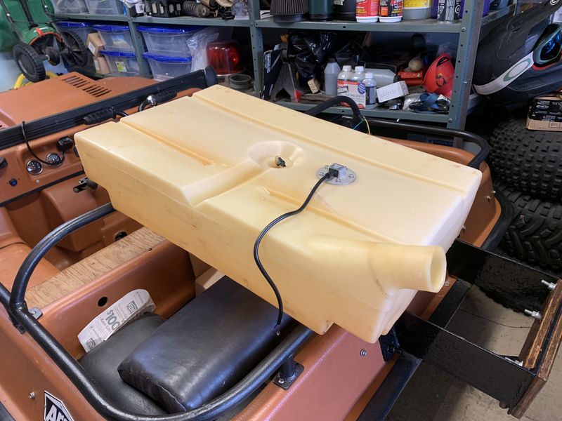
Next I drilled an appropriate sized hole in the gas tank to mount the 150mm sending unit. since the tank was dead empty and been venting now for over 4 months, I used my shop vac to remove all cuttings from drilling the hole.
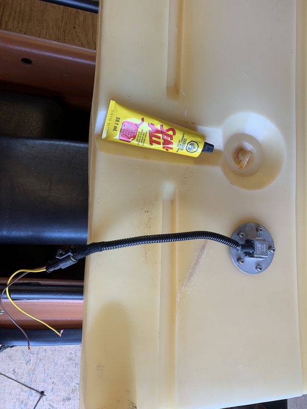
I used my own stainless hardware to bolt the unit in place by drilling small holes and letting the bolts self thread into the plastic.
The unit came with a rubber gasket but I wanted some extra insurance so I coated both sides of the gasket with Seal All, and coated each stainless bolt creating a great permanent seal around the sending unit.
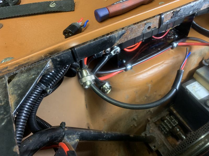
The last step in this wiring project was permanently installing the winch mini rocker switch wiring. I hate long bundled extra cable so once I ran the wire I removed the connector, de-soldered the pins, cut the cable to length and reinstalled the connector for a neat tidy final installation.
November 2019 update:
While moose hunting we were often driving in pre dawn darkness and coming out of the woods after sundown. I found that my upgraded LED headlights were really only effective for about 40-50 feet. When I built my new electrical system I prewired and installed a switch and relay for an auxiliary light bar so now was the time to upgrade!
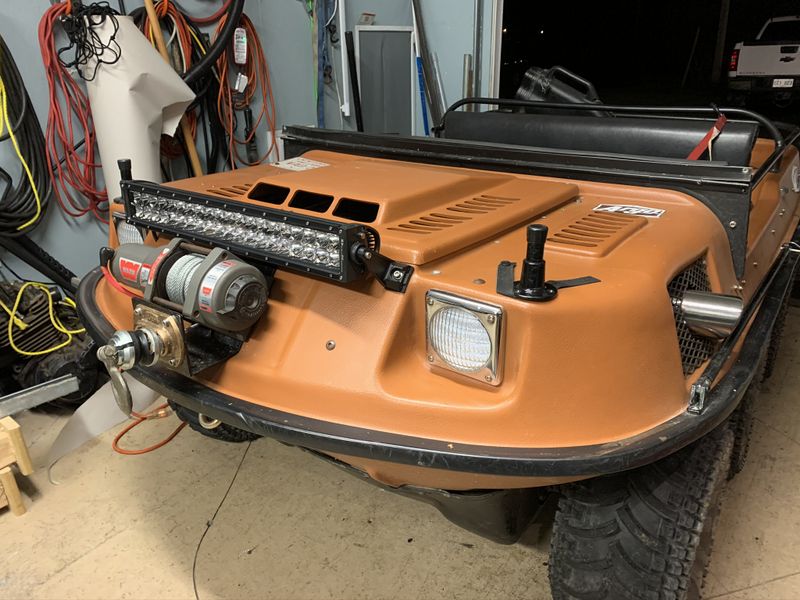
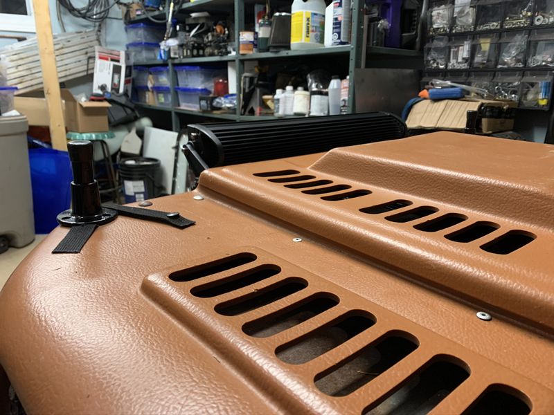
The mounting points for this 22" Duraseries LED light bar from NL Lightbars (not a sponsor) actually lined up perfectly with two aluminum body rivets. I drilled out the rivets, enlarged the holes, and installed the bar with Stainless Steel hardware. A quick two wire splice and the light was in service.
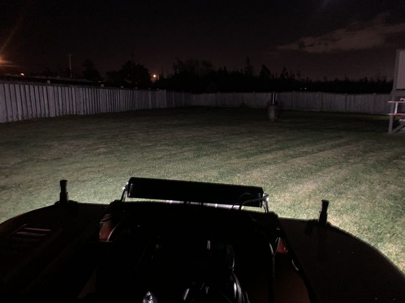
Upgraded LED replacement headlight bulbs only.
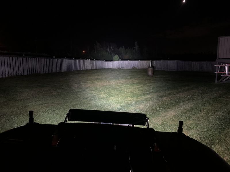
Upgraded LED replacement headlight bulbs plus the 22" Light Bar.
Project Pages: Copyright © 2011 Michael Smith
|
